OUT OF STOCK. Do NOT Order. This item is currently out of stock and will not ship.
4 Axis 36V 4.0A(max.) Drive Box
If you have any questions, feel free to e-mail: support@xylotex.com
Can be used with our
BeagleBox to run a complete CNC System for CNC Wood Routers or small CNC Sherline or Taig Mills.
Comes with the IEC 120VAC power cable. Use an IDC26 cable to apply signals to the DriveBox. If you use the BeagleBox as a CNC Controller for the DriveBox, an
IDC26 to IDC26 Ribbon Cable will suffice.
Shipping labels will be generated through Paypal. Paypal will e-mail you when the labels have been generated. You can also check your Paypal account for the USPS tracking information.
The shipping cost will be $17.50 via USPS 2-3 day Priority Shipping.
NO international shipping at this time (do not place international orders).
The drive box ships 1-2
business days after ordering.
Used for 4 axis, Dual Screw, Gantry type CNC routers, or CNC Mills with a Rotary Axis. 4th axis use is not specifically required, will run with 3 motor just fine as well.
Software use such as
MachineKit,Mach3/4, LinuxCNC, UC100/300 should contact their respective user applications help. See below for specific information regarding the pinout for the drive box.
* 1/16th step (microstep) for smooth, precise motion.
* Four Built-in Cooling Fans
* The higher voltage drive (36V) and higher amperage motors (4.0A) means you can have a faster top end speed compared to lower voltage/amperage drive/motor combinations.
STEP & DIR Setup
The image below shows the specific pinout on the IDC26 connector.
A direct connect to another IDC26 header such as the
Xylotex BeagleBox, a SmoothStepper or UC100 provide, can use a straight-through
IDC26 Ribbon cable.
Alternatively, you can use a
DB25-M to IDC26 ribbon cable to connect the DriveBox to a standard Parallel Port.
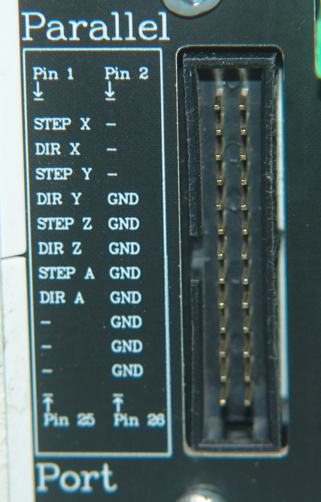
The corresponding Parallel Port DB25 connected to a PC parallel port is a follows:
STEP X - Pin 2
DIR X - Pin 3
STEP Y - Pin 4
DIR Y - Pin 5
STEP Z - Pin 6
DIR Z - Pin 7
STEP A - Pin 8
DIR A - Pin 9
GND Pins 18-25
The DIR line need to be stable 200nS before and after the Rising (active high) edge of the STEP line. The STEP line is of Active High (+) polarity.
To gain access to the extra I/O from the signal port (for attaching limits switches, etc.), you can use an external breakout board such as this
IDC26 Breakout Board or this
DB25 Breakout Board
. The drive box plays NO role in processing other I/O such as Limit/Home/Stop/Probe inputs or other outputs.
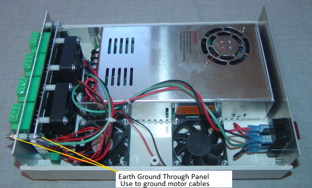
Inside view showing drive board, fans, power supply and wiring.
Use the bolt and nut in the top right hand corner of the panel (see first image above) to ground your motor cables (shielding surrounding the conductors). This can help reduce radiated noise, and help protect the wiring from errant static discharges (see more below).
Vref Setup for Motor Amperage
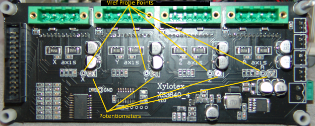
Motor Amps X 0.45V to give proper Vref Setting.
Ex. 4.0A motor X 0.45V = 1.8V Vref Setting.
Do NOT exceed 1.8V on Vref.
Black Probe to the probe point labeled
GND near the X Vref Probe point
Red Probe to the Vref hole near the axis label:
X Y Z A
Motor Wiring
The motor wiring must be properly configured. Mis-wiring can cause
immediate drive board destruction. Each axis has pins labeled similar to the X axis:
X_A
X_A#
X_B
X_B#
One phase of the motor can attach to the A and A# connections. The other phase to the B and B#. The drive is -bipolar-, so which orientation of the A or A# is to use for that phase is not important. What is important, is that the A and B wiring is not crossed.
IMPORTANT NOTES:
Dust can accumulate on the internal heatsinks and inside the fan components (clogging and thus stopping the fan), therefore keep the drive box in a
DUST FREE ENVIRONMENT. For example, build an enclosure for the box using Furnace Filters. Accumulated dust inside can cause drive overheating or fan destruction leading to more heating issues, thus lowering the life of all of the components.
* Keep the drive box bottom up at least 1/2 inch to allow cooler air to be drawn in and warmer air to be expelled.
* Keep coolant, dust and chips away from the system. Small metallic “dust” and chips can easily be pulled in by a fan and deposited on the drive board, shorting it out!
* If you are using a vacuum system(recommended), it
MUST be properly grounded to dissipate static build-up. This means the inside length of the vacuum hose has a flexible bare copper ground wire running the length and
Earth Grounded at the vacuum motor end!
Do NOT connect or disconnect motors when the system is powered.
Do NOT place a fuse, switch, relay or circuit breaker between the motors and the drive box.
Do NOT connect scopes or any other test devices to the motor leads.
If you have any questions, e-mail: support@xylotex.com
10-AUG-2022
